> ## Documentation Index
> Fetch the complete documentation index at: https://docs.stopbars.com/llms.txt
> Use this file to discover all available pages before exploring further.
# Guide
# Configuring BARS for EuroScope
This guide includes a conceptual introduction to the BARS system, the model used
by the EuroScope client, and the process of administering aerodrome data via the
BARS for EuroScope editor. It is aimed at division staff configuring the BARS
plugin for their aerodromes, as well as prospective contributors and others
desiring a technical understanding of the plugin internals.
## BARS Overview
BARS is a system which permits controllers to control the appearance of variable
scenery **objects** (invariably aerodrome ground lights) for pilots.
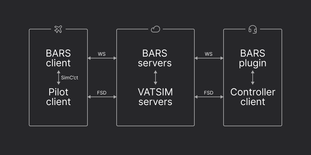
BARS operates as a network separate from the main VATSIM network, similarly to
other peripheral systems (like Audio for VATSIM). The BARS clients attach to the
relevant VATSIM client – pilot clients for pilots, or EuroScope for controllers
– and connect them to the central BARS servers. The servers are responsible for
verifying the state of clients against the VATSIM servers, and conveying data
between all connected clients.
To use BARS, controllers must connect to the BARS network at one or more
aerodromes under their control. These controllers may then send updates to the
state of individual lights, setting them on or off. The BARS server forwards
these updates to any pilots at the relevant aerodrome, and the changes are
displayed to the pilot in the scenery.
To do this, two sets of data are required.
The addition of the EuroScope configuration increases this to three, but the first is directly associated with, and is edited alongside, the EuroScope configuration.
The first is thce **canonical object data**. It consists of the approximate
geographic locations of the objects, and their basic properties: lighting
colour, directionality, etc. Each object is here assigned a unique **BARS ID**,
which starts with `BARS_`. This data is defined by the nominated division
staff members for each aerodrome they wish to be added to the BARS network. Only
those division members with the requisite permissions are able to submit and
edit this data. For divisions using the EuroScope client, this data is edited
and submitted by using the EuroScope data editor.
The second is the **scenery position data**. This data derives from the
canonical data, but is specific to a given scenery for an aerodrome; thus,
whilst each aerodrome has only one set of canonical object data, it may have
many scenery position data sets, for each of the available scenery providers.
It specifies the actual displayed location of the objects (since this may vary
slightly between scenery providers), but not how they appear. This data is
provided by third-party contributors working from the canonical data.
## The EuroScope Model
Due to the relative complexity of lighting systems used outside Australia,
particularly of "follow-the-greens" selective lighting systems, the EuroScope
client for BARS defines are more abstract model of lighting control which
permits greater flexibility. Thus, a third data set is required: the **Euroscope
configuration**.
### Graphs
Instead of having controllers set the state of lights directly, the EuroScope
client keeps track of a **lighting graph**, which is edited by the controller.
The state of individual lights is then computed based on the lighting graph. For
example, if a controller wishes to lower a stopbar, the object displaying the
red stopbar must be set to the *off* state, and the lead-on lights behind it
must be set to the *on* state. Rather than treating these as separate actions,
the EuroScope client considers the two lights to be controlled by one element of
the lighting graph; so, when the controller changes the state of this element in
the graph, both lights change accordingly as one operation.
The "graph" in "lighting graph" refers to the [mathematical sense](https://en.wikipedia.org/wiki/Graph_\(discrete_mathematics\)) and not that of a chart used for data visualisation.
When a controller changes the graph, it is the graph that is synchronised with
other controllers at the aerodrome, not the calcualted state of the lights. This
lets controllers more accurately see the state of the aerodrome, and better
reflects the way real-world systems work.
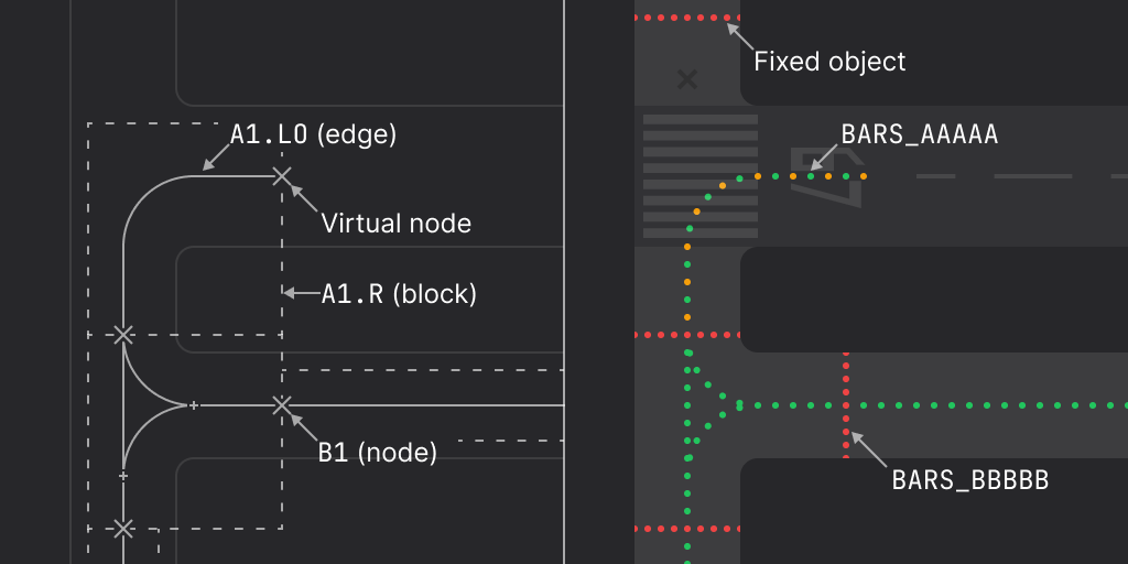
The graph for each aerodrome consists of three types of element: **nodes**,
**edges**, and **blocks**. Objects are linked to **either** one node or one edge
in the graph, or are set to a fixed state (on or off). Objects that are not
linked to any element are called **fixed** objects. Elements that are not linked
to any object are called **virtual** elements. Every element is assigned a
unique **EuroScope ID**.
For those familiar with the mathematical definition, the lighting
graph is formally defined as a possibly-disconnected undirected simple graph,
where nodes have their usual definitions. Edges may be edges in the graph, or
may actually be disconnected nodes. Loops are not permitted. The routing graph
may contain additional unlabeled nodes which are not considered nodes in the
lighting graph. Blocks are connected subgraphs where the edge sets of all blocks
for an aerodrome are disjoint. The difference in the edge set between a block and the
equivalent induced subgraph must either be empty or a subset of another block.
Blocks may partially or wholly orienting, in which case the overall graph is
permitted to be a multigraph with up to two parallel edges per node pair as
long as each is oriented in opposite directions by the associated block.
A node is a "point" in the graph; it usually represents a stopbar. Nodes may be
disconnected, or they can connect to other nodes via edges. A node is used for a
light where the controller should be able to directly control it (such as runway
holding point stopbars), or it is the terminus of a route (at block boundaries
in follow-the-greens). The state of a node is Boolean: either on or off.
An edge is a "line" in the graph; it usually represents a taxiway centreline. An
edge is used for a light where its state is determined by the state of a node
(the lead-on lights following a stopbar, which are interlocked therewith), or
the that of a route (centrelines in follow-the-greens). Controllers can only
indirectly set the state of edges; they are considered outputs, not inputs. The
state of an edge is Boolean: either on or off.
For follow-the-greens only, blocks are defined to permit routes to be drawn
across the aerodrome. A block is a group of nodes and edges representing the
smallest, indivisible segment of a route. Usually, blocks map one-to-one with
routing blocks (sometimes known by other names, such as "maintenance blocks") in
the real world. Blocks touch each other at nodes, and routes are set by joining
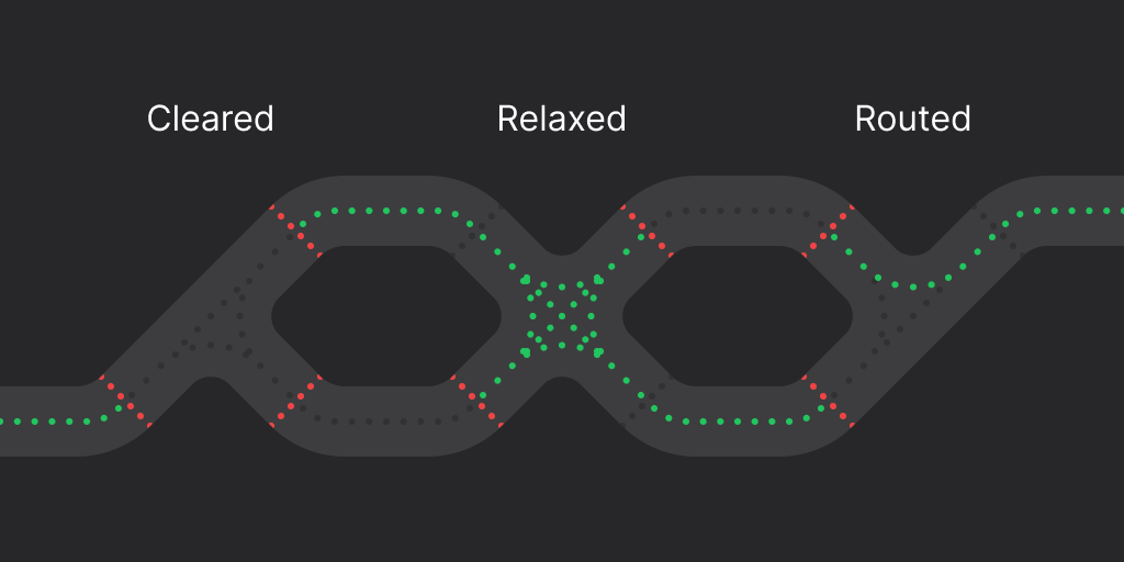
up routes within individual blocks. A block can have three states:
* **cleared**, where no route is set through the block and all centrelines are
off;
* **relaxed**, where no specific route is set through the block, but all routes
are enabled and all centrelines are on; and
* **routed**, where an *ordered* pair of nodes associated with the block are
nominated as the start and end points of the route segment.
### Profiles
Each aerodrome, in addition to its graph, is assigned one or more **profiles**.
Profiles determine how the geometry of the graph is used to calculate the state
of lights, and how controllers interact with the graph. Whilst they cannot
change the shape of the graph itself, they can still significantly affect how
the aerodrome lights function, with unlimited flexibility. Profiles can be used
to define different modes of using the lights, such as a "daytime" mode with
only runway stopbars in use, and a "low visibility" mode which enables FTGs.
When BARS is in use at an aerodrome, only one profile is active at any time. If
a controller changes the profile in use, this change is seen by all other
controllers at the aerodrome.
A profile is defined by a fixed identifier, and a human-readable name that the
controller sees. Each profile contains the **condition** for every element in
the aerodrome graph, and zero or more **presets**.
Nodes can be in one of three conditions:
* **fixed** sets the node to a fixed state of either on or off;
* **direct** makes the node directly settable by the controller, who can toggle
it on or off by clicking it; and
* **router** indicates that the node should be used as a FTGs node, where
setting the associated **sticky** attribute indiciates that the node must be
clicked individually as part of a route, and can not be auto-routed through.
Edges can be in one of three conditions:
* **fixed** sets the edge to a fixed state of either on or off;
* **direct** makes the edge's state the result of a Boolean expression of node
states in
[disjunctive normal form](https://en.wikipedia.org/wiki/Disjunctive_normal_form);
and
* **router** indicates that the edge should be used as a FTGs edge.
Blocks can be either activated or deactivated, but this is residual and implied
by whether any of their associated nodes and edges are in router mode.
Nodes in direct mode and active blocks can have a **reset time** specified as
part of the condition. When the node is set to the off state, or a route is set
through the block, a countdown is started, after which time the node/block is
reset.
Presets consist of a human-readable name and a list of nodes and blocks. When
selected by a controller, the preset will set these elements to the specified
states. This can be used to, for example, define a sane "default" state, or
standard follow-the-greens routes.
### Router Mode
The router mode is the engine which powers the follow-the-greens logic. In
theory, the router would construct routes between nodes by tracing routes along
edges, and illuminating the shortest/best path. However, for various reasons,
and in line with real-world systems, these routes are instead calculated in
advance and "baked" into the configuration. Thus, when picking routes, the
router ignores the actual edges in the aerodrome graph, and replaces them with
edges defined by the blocks.
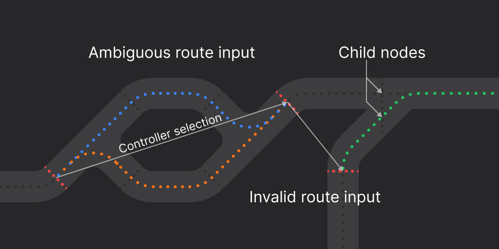
The controller sets a route by clicking nodes in router mode in sequence. The
router will attempt to find a route between the selected nodes, routing through
multiple blocks if possible. This process can fail in two ways: if the route
endpoints selected have multiple possible routes therebetween, the input is
**ambiguous** and fails; if the required route through a block is not permitted
by the block (typically as a result of taxiway geometry), or the two endpoints
are otherwise disconnected in the taxiway network, the input is **invalid** and
also fails.
There exists some additional complexity when a stopbar at the border of a block
is crossed by multiple centrelines. In this case, **child nodes** are created
for each of the intersections at the node, which becomes known as the **parent**
node. This is handled transparently in configuration, and is solved at runtime
by the router.
Sometimes, it may be necessary to have routes be settable through multiple
blocks, but without allowing routes to terminate at certain intermediate nodes.
The prototypical example of this is for routes set at runway holding points with
both standard and ILS hold lines. When the ILS hold lines are not in use, it
should not be possible to set a route terminating thereat; similarly, when they
are in use, it should not be possible to set a route terminating at the standard
line. To achieve this, the node pertaining to the line not in use should have
its condition set to fixed-off in the relevant profile. It will then be ignored
when the router attempts to find a route, and will not be displayed to the
controller.
For a given set route, the resultant states of nodes and blocks is defined by
basic rules. Each node in router mode is off only if there is a route set going
"through" the node; that is, in both blocks on each side of the node, a route is
set which contains the node. Each edge in router mode is on only if, for the
block containing the edge, the block is relaxed, or the pair of nodes defining
the route in the block is contained within a list of matching pairs associated
with the edge.
### Maps
The maps define how elements (not objects) are shown to the controller. Each
aerodrome can have one geographic map, defined in terms of geographic
coordinates and drawn on the EuroScope radar (SMR), and zero or more standalone
non-geographic maps, defined in Cartesian coordinates and drawn on a separate
lighting panel.
Non-geographic maps can define a **background** colour and **base** map
consisting of static vectors.
All maps then contain vector layers for nodes, edges, and blocks; for nodes,
these layers are the off, on, and selected states, plus the hotspot polygon used
to click the node; for edges, these layers are the off, on, and pending states;
for blocks, this is the hotspot polygon used to click the block. All of these
can be empty if the element should not be visible, or should not be
interactable.
It may be desirable in some cases for controllers to have a
"read-only" view of the aerodrome lights, particularly in the SMR view.
However, It is not necessary for divisions to configure maps with no targets
for this purpose, as the plugin provides this functionality natively.
All maps can then contain a layer of **widgets**. The available select of
widgets is liable to change, so they are not listed in detail here; they should
be configured using the EuroScope data editor.
Non-geographic maps must define a list of **views**. Each view has a name and
an axis-aligned rectangle defining the viewport. Controllers are asked to select
a view (not a map) when opening a lighting panel ASR, from the aggregate list of
all views for all non-geographic maps for the current aerodrome.
## The EuroScope Data Editor
The [EuroScope data editor](https://euroscope.stopbars.com/) is the only
recommended means by which divisions using the EuroScope plugin should configure
it and edit their canonical object data.
For guidance on using the editor, please see the tutorial video.
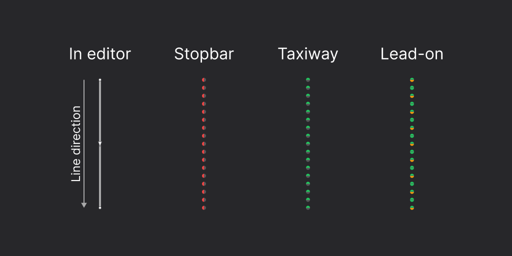
Note that unidirectional lights are generated based on the order of their
points when drawn.
## Distributing BARS
It is recommended that divisions provide a copy of the BARS plugin and the
necessary configuration files as part of their controller pack. Whilst the
plugin does update itself, and so existing users need not install new versions
of the loader, it is recommended that divisions keep the loader they distribute
up-to-date.
The BARS plugin should be placed in its own directory in the pack. By
convention, this is named "bars", but this is not mandatory. Within this
directory, three configuration files are of note.
Further documentation pertaining to configuration will be provided soon.
 To use BARS, controllers must connect to the BARS network at one or more
aerodromes under their control. These controllers may then send updates to the
state of individual lights, setting them on or off. The BARS server forwards
these updates to any pilots at the relevant aerodrome, and the changes are
displayed to the pilot in the scenery.
To do this, two sets of data are required.
To use BARS, controllers must connect to the BARS network at one or more
aerodromes under their control. These controllers may then send updates to the
state of individual lights, setting them on or off. The BARS server forwards
these updates to any pilots at the relevant aerodrome, and the changes are
displayed to the pilot in the scenery.
To do this, two sets of data are required.
 For those familiar with the mathematical definition, the lighting
graph is formally defined as a possibly-disconnected undirected simple graph,
where nodes have their usual definitions. Edges may be edges in the graph, or
may actually be disconnected nodes. Loops are not permitted. The routing graph
may contain additional unlabeled nodes which are not considered nodes in the
lighting graph. Blocks are connected subgraphs where the edge sets of all blocks
for an aerodrome are disjoint. The difference in the edge set between a block and the
equivalent induced subgraph must either be empty or a subset of another block.
Blocks may partially or wholly orienting, in which case the overall graph is
permitted to be a multigraph with up to two parallel edges per node pair as
long as each is oriented in opposite directions by the associated block.
A node is a "point" in the graph; it usually represents a stopbar. Nodes may be
disconnected, or they can connect to other nodes via edges. A node is used for a
light where the controller should be able to directly control it (such as runway
holding point stopbars), or it is the terminus of a route (at block boundaries
in follow-the-greens). The state of a node is Boolean: either on or off.
An edge is a "line" in the graph; it usually represents a taxiway centreline. An
edge is used for a light where its state is determined by the state of a node
(the lead-on lights following a stopbar, which are interlocked therewith), or
the that of a route (centrelines in follow-the-greens). Controllers can only
indirectly set the state of edges; they are considered outputs, not inputs. The
state of an edge is Boolean: either on or off.
For follow-the-greens only, blocks are defined to permit routes to be drawn
across the aerodrome. A block is a group of nodes and edges representing the
smallest, indivisible segment of a route. Usually, blocks map one-to-one with
routing blocks (sometimes known by other names, such as "maintenance blocks") in
the real world. Blocks touch each other at nodes, and routes are set by joining
up routes within individual blocks. A block can have three states:
* **cleared**, where no route is set through the block and all centrelines are
off;
* **relaxed**, where no specific route is set through the block, but all routes
are enabled and all centrelines are on; and
* **routed**, where an *ordered* pair of nodes associated with the block are
nominated as the start and end points of the route segment.
For those familiar with the mathematical definition, the lighting
graph is formally defined as a possibly-disconnected undirected simple graph,
where nodes have their usual definitions. Edges may be edges in the graph, or
may actually be disconnected nodes. Loops are not permitted. The routing graph
may contain additional unlabeled nodes which are not considered nodes in the
lighting graph. Blocks are connected subgraphs where the edge sets of all blocks
for an aerodrome are disjoint. The difference in the edge set between a block and the
equivalent induced subgraph must either be empty or a subset of another block.
Blocks may partially or wholly orienting, in which case the overall graph is
permitted to be a multigraph with up to two parallel edges per node pair as
long as each is oriented in opposite directions by the associated block.
A node is a "point" in the graph; it usually represents a stopbar. Nodes may be
disconnected, or they can connect to other nodes via edges. A node is used for a
light where the controller should be able to directly control it (such as runway
holding point stopbars), or it is the terminus of a route (at block boundaries
in follow-the-greens). The state of a node is Boolean: either on or off.
An edge is a "line" in the graph; it usually represents a taxiway centreline. An
edge is used for a light where its state is determined by the state of a node
(the lead-on lights following a stopbar, which are interlocked therewith), or
the that of a route (centrelines in follow-the-greens). Controllers can only
indirectly set the state of edges; they are considered outputs, not inputs. The
state of an edge is Boolean: either on or off.
For follow-the-greens only, blocks are defined to permit routes to be drawn
across the aerodrome. A block is a group of nodes and edges representing the
smallest, indivisible segment of a route. Usually, blocks map one-to-one with
routing blocks (sometimes known by other names, such as "maintenance blocks") in
the real world. Blocks touch each other at nodes, and routes are set by joining
up routes within individual blocks. A block can have three states:
* **cleared**, where no route is set through the block and all centrelines are
off;
* **relaxed**, where no specific route is set through the block, but all routes
are enabled and all centrelines are on; and
* **routed**, where an *ordered* pair of nodes associated with the block are
nominated as the start and end points of the route segment.
 ### Profiles
Each aerodrome, in addition to its graph, is assigned one or more **profiles**.
Profiles determine how the geometry of the graph is used to calculate the state
of lights, and how controllers interact with the graph. Whilst they cannot
change the shape of the graph itself, they can still significantly affect how
the aerodrome lights function, with unlimited flexibility. Profiles can be used
to define different modes of using the lights, such as a "daytime" mode with
only runway stopbars in use, and a "low visibility" mode which enables FTGs.
When BARS is in use at an aerodrome, only one profile is active at any time. If
a controller changes the profile in use, this change is seen by all other
controllers at the aerodrome.
A profile is defined by a fixed identifier, and a human-readable name that the
controller sees. Each profile contains the **condition** for every element in
the aerodrome graph, and zero or more **presets**.
Nodes can be in one of three conditions:
* **fixed** sets the node to a fixed state of either on or off;
* **direct** makes the node directly settable by the controller, who can toggle
it on or off by clicking it; and
* **router** indicates that the node should be used as a FTGs node, where
setting the associated **sticky** attribute indiciates that the node must be
clicked individually as part of a route, and can not be auto-routed through.
Edges can be in one of three conditions:
* **fixed** sets the edge to a fixed state of either on or off;
* **direct** makes the edge's state the result of a Boolean expression of node
states in
[disjunctive normal form](https://en.wikipedia.org/wiki/Disjunctive_normal_form);
and
* **router** indicates that the edge should be used as a FTGs edge.
Blocks can be either activated or deactivated, but this is residual and implied
by whether any of their associated nodes and edges are in router mode.
Nodes in direct mode and active blocks can have a **reset time** specified as
part of the condition. When the node is set to the off state, or a route is set
through the block, a countdown is started, after which time the node/block is
reset.
Presets consist of a human-readable name and a list of nodes and blocks. When
selected by a controller, the preset will set these elements to the specified
states. This can be used to, for example, define a sane "default" state, or
standard follow-the-greens routes.
### Router Mode
The router mode is the engine which powers the follow-the-greens logic. In
theory, the router would construct routes between nodes by tracing routes along
edges, and illuminating the shortest/best path. However, for various reasons,
and in line with real-world systems, these routes are instead calculated in
advance and "baked" into the configuration. Thus, when picking routes, the
router ignores the actual edges in the aerodrome graph, and replaces them with
edges defined by the blocks.
The controller sets a route by clicking nodes in router mode in sequence. The
router will attempt to find a route between the selected nodes, routing through
multiple blocks if possible. This process can fail in two ways: if the route
endpoints selected have multiple possible routes therebetween, the input is
**ambiguous** and fails; if the required route through a block is not permitted
by the block (typically as a result of taxiway geometry), or the two endpoints
are otherwise disconnected in the taxiway network, the input is **invalid** and
also fails.
There exists some additional complexity when a stopbar at the border of a block
is crossed by multiple centrelines. In this case, **child nodes** are created
for each of the intersections at the node, which becomes known as the **parent**
node. This is handled transparently in configuration, and is solved at runtime
by the router.
### Profiles
Each aerodrome, in addition to its graph, is assigned one or more **profiles**.
Profiles determine how the geometry of the graph is used to calculate the state
of lights, and how controllers interact with the graph. Whilst they cannot
change the shape of the graph itself, they can still significantly affect how
the aerodrome lights function, with unlimited flexibility. Profiles can be used
to define different modes of using the lights, such as a "daytime" mode with
only runway stopbars in use, and a "low visibility" mode which enables FTGs.
When BARS is in use at an aerodrome, only one profile is active at any time. If
a controller changes the profile in use, this change is seen by all other
controllers at the aerodrome.
A profile is defined by a fixed identifier, and a human-readable name that the
controller sees. Each profile contains the **condition** for every element in
the aerodrome graph, and zero or more **presets**.
Nodes can be in one of three conditions:
* **fixed** sets the node to a fixed state of either on or off;
* **direct** makes the node directly settable by the controller, who can toggle
it on or off by clicking it; and
* **router** indicates that the node should be used as a FTGs node, where
setting the associated **sticky** attribute indiciates that the node must be
clicked individually as part of a route, and can not be auto-routed through.
Edges can be in one of three conditions:
* **fixed** sets the edge to a fixed state of either on or off;
* **direct** makes the edge's state the result of a Boolean expression of node
states in
[disjunctive normal form](https://en.wikipedia.org/wiki/Disjunctive_normal_form);
and
* **router** indicates that the edge should be used as a FTGs edge.
Blocks can be either activated or deactivated, but this is residual and implied
by whether any of their associated nodes and edges are in router mode.
Nodes in direct mode and active blocks can have a **reset time** specified as
part of the condition. When the node is set to the off state, or a route is set
through the block, a countdown is started, after which time the node/block is
reset.
Presets consist of a human-readable name and a list of nodes and blocks. When
selected by a controller, the preset will set these elements to the specified
states. This can be used to, for example, define a sane "default" state, or
standard follow-the-greens routes.
### Router Mode
The router mode is the engine which powers the follow-the-greens logic. In
theory, the router would construct routes between nodes by tracing routes along
edges, and illuminating the shortest/best path. However, for various reasons,
and in line with real-world systems, these routes are instead calculated in
advance and "baked" into the configuration. Thus, when picking routes, the
router ignores the actual edges in the aerodrome graph, and replaces them with
edges defined by the blocks.
The controller sets a route by clicking nodes in router mode in sequence. The
router will attempt to find a route between the selected nodes, routing through
multiple blocks if possible. This process can fail in two ways: if the route
endpoints selected have multiple possible routes therebetween, the input is
**ambiguous** and fails; if the required route through a block is not permitted
by the block (typically as a result of taxiway geometry), or the two endpoints
are otherwise disconnected in the taxiway network, the input is **invalid** and
also fails.
There exists some additional complexity when a stopbar at the border of a block
is crossed by multiple centrelines. In this case, **child nodes** are created
for each of the intersections at the node, which becomes known as the **parent**
node. This is handled transparently in configuration, and is solved at runtime
by the router.
 Sometimes, it may be necessary to have routes be settable through multiple
blocks, but without allowing routes to terminate at certain intermediate nodes.
The prototypical example of this is for routes set at runway holding points with
both standard and ILS hold lines. When the ILS hold lines are not in use, it
should not be possible to set a route terminating thereat; similarly, when they
are in use, it should not be possible to set a route terminating at the standard
line. To achieve this, the node pertaining to the line not in use should have
its condition set to fixed-off in the relevant profile. It will then be ignored
when the router attempts to find a route, and will not be displayed to the
controller.
For a given set route, the resultant states of nodes and blocks is defined by
basic rules. Each node in router mode is off only if there is a route set going
"through" the node; that is, in both blocks on each side of the node, a route is
set which contains the node. Each edge in router mode is on only if, for the
block containing the edge, the block is relaxed, or the pair of nodes defining
the route in the block is contained within a list of matching pairs associated
with the edge.
### Maps
The maps define how elements (not objects) are shown to the controller. Each
aerodrome can have one geographic map, defined in terms of geographic
coordinates and drawn on the EuroScope radar (SMR), and zero or more standalone
non-geographic maps, defined in Cartesian coordinates and drawn on a separate
lighting panel.
Non-geographic maps can define a **background** colour and **base** map
consisting of static vectors.
All maps then contain vector layers for nodes, edges, and blocks; for nodes,
these layers are the off, on, and selected states, plus the hotspot polygon used
to click the node; for edges, these layers are the off, on, and pending states;
for blocks, this is the hotspot polygon used to click the block. All of these
can be empty if the element should not be visible, or should not be
interactable.
Sometimes, it may be necessary to have routes be settable through multiple
blocks, but without allowing routes to terminate at certain intermediate nodes.
The prototypical example of this is for routes set at runway holding points with
both standard and ILS hold lines. When the ILS hold lines are not in use, it
should not be possible to set a route terminating thereat; similarly, when they
are in use, it should not be possible to set a route terminating at the standard
line. To achieve this, the node pertaining to the line not in use should have
its condition set to fixed-off in the relevant profile. It will then be ignored
when the router attempts to find a route, and will not be displayed to the
controller.
For a given set route, the resultant states of nodes and blocks is defined by
basic rules. Each node in router mode is off only if there is a route set going
"through" the node; that is, in both blocks on each side of the node, a route is
set which contains the node. Each edge in router mode is on only if, for the
block containing the edge, the block is relaxed, or the pair of nodes defining
the route in the block is contained within a list of matching pairs associated
with the edge.
### Maps
The maps define how elements (not objects) are shown to the controller. Each
aerodrome can have one geographic map, defined in terms of geographic
coordinates and drawn on the EuroScope radar (SMR), and zero or more standalone
non-geographic maps, defined in Cartesian coordinates and drawn on a separate
lighting panel.
Non-geographic maps can define a **background** colour and **base** map
consisting of static vectors.
All maps then contain vector layers for nodes, edges, and blocks; for nodes,
these layers are the off, on, and selected states, plus the hotspot polygon used
to click the node; for edges, these layers are the off, on, and pending states;
for blocks, this is the hotspot polygon used to click the block. All of these
can be empty if the element should not be visible, or should not be
interactable.
 ## Distributing BARS
It is recommended that divisions provide a copy of the BARS plugin and the
necessary configuration files as part of their controller pack. Whilst the
plugin does update itself, and so existing users need not install new versions
of the loader, it is recommended that divisions keep the loader they distribute
up-to-date.
The BARS plugin should be placed in its own directory in the pack. By
convention, this is named "bars", but this is not mandatory. Within this
directory, three configuration files are of note.
Further documentation pertaining to configuration will be provided soon.
## Distributing BARS
It is recommended that divisions provide a copy of the BARS plugin and the
necessary configuration files as part of their controller pack. Whilst the
plugin does update itself, and so existing users need not install new versions
of the loader, it is recommended that divisions keep the loader they distribute
up-to-date.
The BARS plugin should be placed in its own directory in the pack. By
convention, this is named "bars", but this is not mandatory. Within this
directory, three configuration files are of note.
Further documentation pertaining to configuration will be provided soon.